The Aerodynamics of the V-bombers – Part 4
Dr Steve Liddle CEng FRAeS, is a Vulcan to the Sky Trustee and Principal Aerodynamicist at Aston Martin Formula One Team. The articles here are
Dr Steve Liddle CEng FRAeS, is a Vulcan to the Sky Trustee and Principal Aerodynamicist at Aston Martin Formula One Team. The articles here are republished from Steve’s occasional series on ‘the aerodynamics of the V-bombers’, that he writes on the Vulcan to the Sky Trust LinkedIn page.
It hasn’t taken long to drift off topic, but I was grateful for Stephen McParlin’s comment on the previous article; inspiring some debate on the technical challenges that were overcome to build the V-Force is what I was hoping to do! Stephen makes the excellent point that the Crescent Wing solution as designed for the Victor was a much more advanced solution than the Vulcan’s delta. I agree that aerodynamically this is almost unarguable, but there is more to it than that. As difficult as it is for me to admit, there may be more to life than aerodynamics.
One of the aims of these articles is to show how much freely available technical information can be accessed online, not only in respect of the V-Force aircraft but many others from the period. I was reminded of a report that I came across during my Ph.D research days, which again shows the strong influence of the Royal Aircraft Establishment in engineering Britain’s airborne nuclear deterrent.
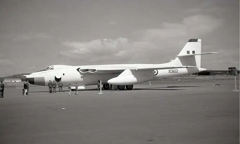
The Victor’s brilliantly executed constant critical Mach number wing was indeed an excellent solution for high speed, high altitude flight. Nonetheless, it suffered from the same problem that can be observed on almost any commercial jet flight today: that wing does not produce enough lift at the low speeds required for sensible take-off and landing distances. To do that, the wing would need to be able to change its shape, a requirement that was sidestepped by the Vulcan’s delta.

Sixty years ago this week, Flight magazine profiled the Victor, describing some of the engineering basis with the caveat that the aircraft was still heavily classified. This made heavy use of Godfrey Lee’s (HP Deputy Chief Designer) 1954 Royal Aeronautical Society lecture and its subsequent coverage in Flight, in describing the aerodynamics of the crescent wing. At low speed (approaching the stall, applicable when considering take-off and landing), the article notes:
“Owing to their limited camber, and small leading-edge radius, this aerofoils have poor low-speed, lift and stall characteristics. Slats were considered to pose greater development problems than did leading-edge flaps, which increase camber and follow the switch shift in stagnation point at high [Lift Coefficient]….. Had the Victor been designed a few years later, it would have had a drooped leading-edge, as has been fitted to the Comet and the Caravelle…”
Here again, as noted previously for the Vulcan, was a tacit admission of how close to the limit of aircraft design HP were working when engineering the Victor. Both leading edge (or nose, as referred at the time) flaps and slats would become common place over the subsequent fifteen or so years, but at the time they certainly were not and few of the contemporary swept-wing aircraft designs (for example, Boeing 367-80 prototype and subsequent KC-135) incorporated them, despite the potential high lift performance advantage.
Flight’s original coverage of the 1954 lecture covered the discussion afterwards, with a comment being made that the, “..nose flaps had proved necessary, but they were worth the complication.” Aircraft design is very much a multi-disciplinary process and there is often a conflict between optimum aerodynamic shape and the resulting structure and implied weight required; the additional performance has to be worth the weight and cost that follow. The leading edge of a wing has to be strong enough to resist bird strike and will contain systems for de-icing, for example, before the additional weight, power and maintenance requirements of the actuation system are considered. Somewhere along the line, the complication of the nose flaps was viewed as an opportunity for development. The final five production Victors were built with a new, extended and cambered but fixed, leading edge and again, we can turn to a contemporary technical report to explain how HP were able to introduce this change.

R.A. Wallis’s report, published in 1965 but discussing work from nearly a decade earlier, starts with the statement that, “This project had its origin in a request from Handley Page Ltd of the probable effectiveness of discrete air jets as a method of boundary-layer control in the ‘Victor’ bomber aircraft. This was associated with a desire to replace the leading edge flaps with a less complex device while maintaining an equal degree of effectiveness as regards maximum lift and aircraft stability”
As the Flight article had said, the challenge was to adapt the high-speed outboard wing section to a different situation; with the angle of the wing to the incoming airflow increased from the cruise position to one that gave high lift, the sharp leading edge caused a rapid acceleration and pressure drop. The air was then faced with an uphill struggle to recover over the remaining chord of the wing back to atmospheric pressure at the training edge, while remaining attached and efficiently maintaining lift. However, at some point as the angle of attack was increased, this pressure gradient would become too great for the boundary layer to negotiate. As this point was approached, the flow would be tempted further outboard as the swept isobars made it see a lower pressure region and hence path of least resistance there. This tended to load the tip of the wing and bring it closer to stall.
While Tip Stall was a major problem for early swept wing aircraft, with the still lifting inboard and hence forward regions of the wing causing pitch up and exacerbating the situation, the problem for the Victor was one of widespread leading edge stall as the wing attempted to generate enough lift. Energising the boundary layer by adding momentum from air jets would have seemed a viable solution. Compared to a fixed droop leading edge, it left the wing section in the optimum shape for cruise and adapted the aerodynamics of the low speed condition to suit it.

The report recounts that although the blowing worked to an extent, it would not have been enough to allow replacement of the flaps. The mass flow of air required was more than anticipated, but it was thought worthwhile to continue the tests to find out what would work, in conjunction with new leading edges designed to be drooped and hence meet the oncoming airflow at a reduced angle. Wallis states that these leading edges alone produced such good performance that the idea of blowing was abandoned. A solution to the problem had been found, in a round-about way.
The actual shape adopted for the Victor was the result of further design iterations with RAE and HP involvement, further building upon Wallis’s work. Reattaching the flow after separation quickly was of vital importance to stability, as was ensuring that the stall occurred somewhere onboard first to avoid pitch up. The air jets had been found to reduce hysteresis and so might again have become part of the solution. However, the new 3% chord extension that would be fitted to the production aircraft solved both these problems by simply ending the extension abruptly at its inboard end. This appeared to trigger stall locally, although the mechanism was not discussed. We might expect a local load increment from the edge vortex, resulting in an initial separation, or perhaps the exaggerated discontinuity from the isobars of the inboard section now that the peak suction outboard had moved forward.
Either way, this work resulted in the required low speed lift being provided without the complexity of either leading edge flaps or air jets. Wallis’s report makes several references to the ease with which the air jets might have been installed. Perhaps! They would have required bleed air from the engines to be ducted to them, which may have been able to be combined with the existing hot air de-icing. That said, the Victor B1 in particular was not renowned for having spare engine capacity available on take-off. Provided that the cruise performance was not compromised (and this is not discussed in the report), then the fixed leading edge would have been hard to beat by any powered system.
So what relevance did this have to a researcher decades later, or indeed it is today? The answer is that there are thousands of moderately swept wing transonic aircraft in service now and we should expect there to be thousands more to be constructed and used in the years ahead. Although blowing systems have never yet been chosen for a commercial jet transport, knowledge of the capabilities of such systems and how they might one day deliver benefit is important in the engineering of ever more efficient and cost effective aircraft. It’s been a long wait, but maybe their day will come. Maybe you’ll be the engineer that achieves it.
The novel delta planform of the Vulcan was tested using small scale research aircraft, the Avro 707s. These were intended to investigate the low speed part of the flight envelope, while the larger Avro 710 would look at high speed and altitude performance. The 710 was cancelled and replaced by a reengineered version of the small aircraft, 707A. Article #2 [add link to ‘Article #2’ https://vulcantothesky.org/news/1042/82/the-aerodynamics-of-v-bombers/News] looked at the leading edge modifications tested on this high speed platform and eventually embodied on the production Vulcan B1.

Using available online technical reports, we can delve into the performance of this aircraft, representative of the original 707, the very first delta to fly in the UK, in 1949. One chart for now, that shows something remarkable: a new regime of high angle of attack capability. This figure shows that the lift curve remained linear up to an incidence in excess of 20deg, while it was still positive in slope at 25deg. Coupled with the relatively efficient surface:volume ratio, structural and configuration design possibilities of the delta, a new age was on its way…
Aerodynamics of the Crescent Wing; Flight 14th May 1954 – Flight Global
Victor: A technical description of Britain’s latest V-bomber; Flight Oct 30th 1959 – Flight Global


Dr Steve Liddle CEng FRAeS, is a Vulcan to the Sky Trustee and Principal Aerodynamicist at Aston Martin Formula One Team. The articles here are

In mid-1956 I returned to England from a two year working holiday in New Zealand and Australia, and urgently needed to replenish my depleted coffers,
William Penney, the man in charge of Britain’s bomb design, William Cook, his deputy, and the scientists at the Atomic Weapons Research Establishment (AWRE) at
Two weeks before the first nuclear weapon was used for warfare, dropped on the Japanese city of Hiroshima, the results of the UK general election